Time-of-Flight (ToF) cameras produce a depth image,each pixel of which encodes the distance to the corresponding point in the scene.
The Time of Flight technique works by illuminating scene with laser projector and detecting reflected light.
There are two technology roadmap of ToF: direct ToF(dToF) based on SPAD (single-photon avalanche diode) technology,while indirect ToF(iToF) using CMOS technology.
We will discuss how to select an appropriate iToF solution this time.
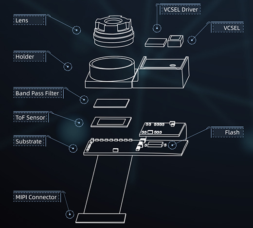
A typical iToF module is consist of several parts that are shown below in pic 1.

VCSEL: Laser projector(wavelength adopting 850nm or 940nm for consumer market in most of time) determine the field of view(FOV) of the module,also is the main heat source of a whole module;
VCSEL Driver: Amplify the modulated signal that comes from the ToF sensor;
Lens: F/NO and FOV is key parameters. A ToF module always need the aperture of lens as large as possible for a better SNR with lower power consumption(Ex.:F/NO 1.0-1.2 is used for domi module).
Band Pass Filter: 850nm or 940nm,coordinate with the wavelength of VCSEL selected.
ToF sensor: Resolution from 100*100 to 640*480,output raw image(IR image) only.
Flash: Every iToF sensor pixel need to be calibrated.The calibration coefficient matrix is stored to flash after a module calibration done.
MIPI Conector: High speed interface is needed because every single frame 3-9 phases of IR raw image data outputs from sensor.
From the description above,we can see there are a few parameters that need to be carefully considered:
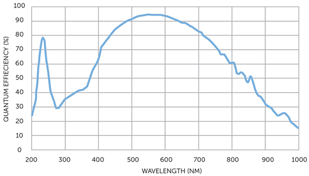
1, Wavelength: 850nm(indoor use) or 940nm(outdoor use). The QE chart(pic 2) below shows the QE of 850nm is nearly 2 times of that of 940nm for ToF sensor,so if choosing 850nm VCSEL,lower power consumption is needed or long distance range with the same power consumption. Of course,850nm ToF module is not suitable for outdoor use because it will cause overexposure easily by sunlight.
2, FOV: Determined mainly by laser projector.There is always tradeoff between FOV and max detection range because we can not simply increase the power of VCSEL for heat sink consideration.
Example: an application scene requires 60*45°/30fps/5m range,then a 3w optical power VCSEL is needed,and the average power consumption will reach 1.5w or more(the Power Conversion Efficiency of VCSEL is only about 40% and will decrease with the temperature going up).But if the FOV is 80*60°/30fps, the max distance is 3m instead of 5m with the same power consumption.
3, Resolution of ToF sensor: The ToF sensor output raw image data from mipi interface and need to be translated into depth data pixel by pixel using an extra processing unit.
The best solution of course is the ToF sensor embedded with depth calculating unit.Unfortunately there is no mature solution yet for bulk order.
There are two ways to connect to your main processor:
3-1, ToF sensor raw data --> depth calculation lib compiled by main processor toolchain(depth calculation lib is unreleased in most case).
This is a complicated task and little ToF sensor company will offer support except for some top customers.Also computing power need to be considered for depth calculation.So ToF sensor companies choose to develop USB or Ethernet interface ToF cameras instead,but it will increase the BOM cost and structure size.
3-2, ToF sensor raw data --> ASIC(ISP) --> depth & IR data(mipi/dvp/spi). A FPGA or ASIC(ISP) is added to avoid coupling deeply between sensor and main processor. The advantage is less task for porting SDK and no need a powerful main processor.
Also some other requirement need to be considered:
1, Measurement Distance min & max : The min distance is between 10-20cm(blind area) if the max distance is less than 3m.
2, Accuracy requirement:Keep in mind that ToF solution is centimeter-level error.Narrow laser pulse width(higher frequency of laser pulse) can improve the accuracy for short distance range.
3, Frame rate: Power consumption consideration for ToF module.

Key parameters of domi ToF sensors:
| Model | Resolution | FOV | Distance range | Wavelength | Max fps | Interface | Remark |
| DMi20(ToF only) | 640*480 | 60*45° | 0.3-5m | 940nm | 15fps | USB only | iToF |
| DM-RGBD-5002A | 640*480 | 64*51° | 0.3-5m | 940nm | 25fps | USB only | iToF |
| DM-RGBD-5003A | 640*480 | 80*66° | 0.3-3m | 940nm | 25fps | USB only | iToF |
| DMOS5031A | 100*100 | 70*50° | 0.2-3m | 940nm | 20fps | SPI | ISP included/iToF |
| DMOM2508PA | 240*320 | 50*70° | 0.15-1.5m | 940nm | 30fps | MIPI | ISP needed/iToF |
| DMOM2508CL | 320*240 | 70*50° | 0.2-2m | 940nm | 30fps | MIPI | ISP needed/iToF |
| DMOM2808D | 320*240 | 70*50° | 0.2-3m/5m | 850nm | 30fps | MIPI | ISP needed/iToF |
| DMOM2006B | 280*170 | 100*60° | 0.2-1m | 850nm | 10fps | MIPI | ISP needed/iToF |
